


Page 72 - newDATAmagazine | 14>06>2022
P. 72
In  Table  2,  it  is  also  presented  the  total    In Table 3, the values of the OSNR with in-
         crosstalk level at the network output, defined         band crosstalk, calculated using
         by


                                                               are shown for WSS isolations of -30 dB and -35
         where P  is the power of the interfering term,        dB and where p =X  x p . These OSNR values
                                                                                        Rx
                  Xc,i
                                                                                    c
                                                                               Xc
         p is the power of the input primary signal, N         are calculated for networks with 10 km spans
          Rx
                                                         Xc
         is the total number of interfering terms, and X       and with 60 km spans, with signal insertion at
                                                         c,i
         is the crosstalk level of the i-th interfering term.  node N1 and extraction at node N2 and with
                                                               signal insertion at node N2 and extraction at
                                                               node N1. At the top of Table 3, the common
                                                               parameters between both cases, such as the
                                                               OSNR  R,min ,  the  power  of  interfering  terms  for
                                                               isolations of -30 and -35 dB, and the parameter
                                                               η NLI   are  presented.  Then,  the  parameters
                                                               associated with each case are shown, such as
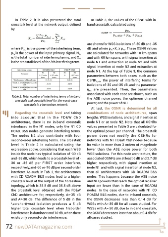
         Table 2: Total number of interfering terms of in-band   the  ASE  noise  power,  the  optimum  channel
            crosstalk and crosstalk level for the worst-case
                  crosstalk in a horseshoe network.            power, and the power of NLI.
                                                                  At  last,  the  OSNR  is  determined  for  all
            Regarding  the  crosstalk  level  and  taking      combinations  of  node  architectures,  span
         into  account  that  in  the  FD&W  ChD               lengths, WSS isolations, and signal insertion at
         architecture,  there  is  no  in-band  crosstalk      node N1 or at node N2. Note that all OSNRs
         introduced  in  the  N1  nodes,  only  the  N1  CD    values presented in Table 3 are calculated for
         ROAD, B&S nodes generate interfering terms.           the optimal power per channel. The crosstalk
         The  nodes  N2  also  contribute  with  four          power  does  not  modify  the  OSNRs  for
         second-order interfering terms. The crosstalk         networks with N1 FD&W ChD nodes because
         level  in  Table  2  is  calculated  using  the       its value is more than 3 orders of magnitude
         expression above, considering that each WSS           lower  than  the  ASE  noise  power  for  both
         inside the node has typical isolation of -30 dB       WSSisolations. For this node architecture, the
         and -35 dB, which leads to a crosstalk level of -     associated OSNRs are at least 6 dB and 2.7 dB
         30  or  -35  dB  per  FIRST  order  interferer,       higher,  respectively,  with  signal  insertion  at
         respectively, and -60 or -70 dB per second-order      node N1 and with signal insertion at node N2,
         interferer. As such, in Tab .2, the architectures     than  all  architectures  with  CD  ROADM  B&S
         with CD ROADM B&S nodes lead to a higher              nodes. This happens because the ASE noise
         crosstalk level at the output of the horseshoe        and NLI powers that reach the optical receiver
         topology, which is 38.5 dB and 35.5 dB above          input  are  lower  than  in  the  case  of  ROADM
         the  crosstalk  level  obtained  with  the  FD&W      nodes.  In  the  case  of  networks  with  N1  CD
         ChD  architecture  for,  respectively,  A=-35  dB     ROADM B&S nodes, due to in-band crosstalk,
         and  A=-30  dB.  The  difference  of  5  dB  in  the   the  OSNR  decreases  less  than  0.14  dB  for
         \acrshort{wss}  isolation  produces  a  5  dB         WSSs with A=-35 dB for all cases studied. For
         higher  total  crosstalk  level  when  first-order     WSSs with A=-30 dB, due to in-band crosstalk,

         interference is dominant and 10 dB, when there        the OSNR decreases less than about 0.4 dB for
         exists only second-order interference.                all cases studied.


     72 newDATAmagazine.com

